Every building project sits on a real piece of ground, with a geographic location, boundaries and survey data held in public map records. In Norway that data lives in the shared map database (FKB), managed by the national mapping authority and providers such as Norkart and Ambita. In Finland it comes from the city base map. Wherever you build, the model has to line up with that data.
Choosing the right coordinate system is what makes that line-up accurate. It matters most on complex projects and on sites that stretch over long distances, where a small projection error compounds into a real one. The two decisions that follow from it are the same everywhere: which national coordinate system to order your map data in, and how to georeference your model so every discipline works in the same place.
How a coordinate system anchors a project
A coordinate system fixes every point on site to a pair of values measured from a known reference. Get the system right at the start and the model, the survey data and the drawings all agree. Get it wrong, or change it midway, and you inherit deviations that are hard to spot until they show up on the building site.
Norway uses two official projections, Euref89 UTM and Euref89 NTM. Each has its place, and each has a trap.
Euref89 UTM
UTM gives coordinates in two dimensions, north and east. Every position is set by two distances: the northing, measured from the equator going north, and the easting, measured from a reference line going east.
UTM treats the earth as a mathematical shape, an ellipsoid, so distances and positions can be measured precisely. But the world is curved and our drawings are flat, so the coordinates have to be projected onto a flat sheet. That projection is never quite free. It can introduce a deviation of up to 4 cm for every 100 m, and the larger the area, the larger the deviation. On big, high-precision projects that is critical.
UTM also has its origin somewhere in West Africa. The distances back to that origin are large, and many tools struggle to hold the precision over them.
Euref89 NTM
NTM was created at the request of the construction industry as a secondary official projection in Norway. It uses a narrower zone width of one degree, which gives better accuracy, and it divides the country into zones 5 to 30.
Its origin sits somewhere in the southern North Sea. To keep day-to-day work simple, a false offset is built in so you never deal with negative numbers. The false northing is 1,000,000 m (N = 1,000,000 at 58° latitude), which makes every northing positive. The false easting is 100,000 m, which does the same for eastings.
Which system to choose
Both UTM and NTM have their strengths and their limits, so the real safeguard is knowing the difference and ordering the right one from the start.
Do not switch from UTM to NTM once a project is under way unless it is strictly necessary. If you have to, be ready for heavy manual work and for deviations that need correcting before the model sits correctly in the new system.
If you order map data in NTM, it has to be converted from UTM, and the conversion uses complex formulas from the national mapping authority. It is better for everyone to confirm the correct coordinate system before the map data is ordered.
Georeferencing in BIM projects
Georeferencing means tying a BIM project to a geographic coordinate system, so the project sits in the right place on the map.
The point of it is collaboration. Architects, engineers and others work in different BIM tools, Archicad, Revit, DDS, Tekla, and they all have to land in the same spot. Agree on where the project origin is and georeference correctly from the start, and every model lines up. That removes the mismatches that otherwise surface during design and on site.
GIS, BIM and CAD do not share the same axes
A BIM and CAD tool like Archicad sets up its coordinate system with the Y axis pointing up and the X axis to the right, with north at 90°, the way a map reads with north up.
A GIS (geographic information system) also runs north along the Y axis and east along the X axis, but the rotation runs the opposite way to a BIM and CAD system, and straight up in GIS is 0°.
Because of that difference, be careful with coordinates. When you build a list of them, label the columns clearly as "North" and "East". SOSI and .kof files always give the north coordinate first, which is worth remembering when you work or convert across platforms.
SOSI files
If you have a SOSI file (the standard format for geographic data in Norway) and are not sure which coordinate system it uses, open it in a text editor and look for the field "KOORDSYS".
KOORDSYS 23 means the file uses Euref89 UTM zone 33. KOORDSYS 210 means it uses NTM zone 10. All NTM zones use three-digit codes.
Height datum and why it matters
The height datum is the reference system for elevations in the map records. In Norway it has been updated several times. Today the standard is NN2000, but earlier projects used NN54 and local municipal datums.
That matters most on rehabilitation and extension projects. Older drawings and detail maps can carry the wrong levels compared with today's base map and updated terrain surveys. The difference between NN54 and NN2000 can be as much as 0.6 m, and some municipal datums deviate even more. Take it into account whenever you work from old plans or commission fresh surveys.
Why you should not deliver in true world coordinates
It is tempting to deliver a BIM model, an IFC for example, in true world coordinates. We do not recommend it, and the requests for it usually come from not seeing the consequences.
The problem is the size of the numbers. Tools like Revit and Archicad have limits on how far from the origin you can model before deviations appear, because the maths gets unwieldy. The result is inaccuracies in measurements and angles that are hard to catch before you are already building.
The answer is to georeference and set up a project origin. Pick a point near where the building will sit and define it as the local zero point of the BIM project. Place that point on a 100-metre grid, ideally to the south-west of the area you are designing, so the coordinates transform cleanly back to the real map coordinates on the original base map.
The project origin should be defined by a GIS-literate architect or consultant, and every party on the project should be told clearly about the coordinates, the height datum and the base map. That shared understanding is what protects accuracy and quality.
Setting up a local coordinate system in your model
This is where the principle becomes a workflow. The example below is Archicad, but the logic carries across tools.
The local coordinate system, also called the project coordinate system, is the project's shared system, the one the models are published in and the combined model is assembled in. Set its origin (0,0,0) relatively close to the building, at sea level (N2000) in height and within a few hundred metres in X and Y, but never inside the building itself.
The common rule is that the whole site should fall in positive coordinate values. So you do not pin the origin to a building corner or a plot corner. Pick a nearby round figure instead, for example the intersection of coordinates ending in 50 or 100 metres.
Models go to building control oriented to map north, like a site plan. A map-north-aligned local coordinate system is likely to be the most common arrangement. Use the correct map north, the one from the city base map in its GK projection, which is slightly different from the polar north a service like Google Maps uses or the magnetic north a compass shows.
The internal coordinate system sits alongside it
Designers also have their own design coordinate system inside their software, the internal coordinate system. Models are not published in it, but it is the practical place to work, and plan drawings are usually published aligned to it.
In Archicad you normally model the building in the internal coordinate system, "straight", and only publish it in the local coordinate system, rotated to map north, using the Survey Point's north direction. DWG drawings can also be published map-north-aligned through the Survey Point, which makes them easier to use with the models.
A shared origin keeps it clean
It works best when the internal origin also acts as the local origin. The Survey Point then sits at the X and Y of the project's internal origin, marked by the black cross in the Archicad template, with the Survey Point on top of it by default. A shared origin makes rotating data to and from map north as clear as possible and cuts the chance of error.
Height position and floor levels
In height, keep the building's first floor (the first above-ground storey) at 0.00 in the internal coordinate system. Early in a project the floor levels relative to sea level are often still being refined, and working this way is the smoothest: a change usually means editing only the sea-level height, not every storey. The real levels are always available by setting the reference to sea level.
The local coordinate origin, though, is placed at sea level, so the Survey Point is given a negative height relative to the internal origin.
One Archicad detail to watch: the "Altitude above sea level" set in Location Settings is a different value from the Survey Point's height. To make it work as the dimensioning reference inside Archicad, so your drawings show levels relative to sea level, you set it separately to match the Survey Point. Only the Survey Point height drives the model's local-coordinate height when it is published. The dimensioning reference level is set under Options > Project Preferences > Reference Levels.
Reference points and alignment objects
Reference points, usually the origin plus two more points, "VP1" and "VP2", are the alignment points that make the local coordinate system usable. Record their values in the base-map GK coordinates in the model report, so any data held in map coordinates can be aligned to the local coordinate system precisely.
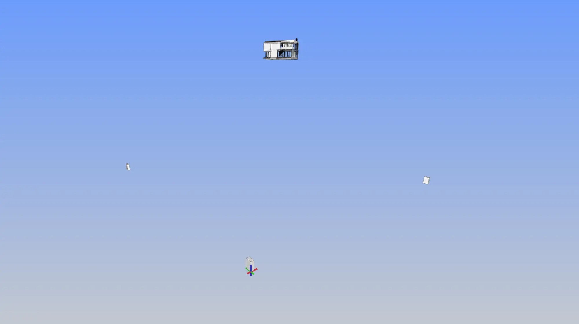
In the model the reference points are shown as alignment objects, so correct alignment in the combined model is easy to confirm by eye.
Creating the reference points
Start by choosing the local origin, the first reference point. Work from a base map that shows the coordinate crosses. Some map data, Cetopo's for example, comes with the coordinate grid included. If the values are not on the map, you can ask the city map unit to mark them or prepare them yourself in DWG.
Choose the origin so the site and its plot lie east and north of it, on the positive axes, and so nothing in the wider model content sits above the origin or the other reference points, since they are easiest to use when they are not hidden behind geometry.
Set the reference points at round map coordinates, eastings and northings ending in 50 or 100 m, which are easier to handle than the large raw numbers. The origin is the first reference point, with VP1 to the east and VP2 to the north, each say 50 or 100 m away. Building geometry shifts during design and plot corners can be refined, so keeping the reference points independent of the actual geometry is the safe choice.
The base map itself is best brought into a worksheet, kept separate from the model and used as a trace reference, so it cannot be edited by accident or cause problems at its large scale. In practice you build three worksheets: one with the map in GK coordinates attached as an external drawing with its origin on the worksheet origin, one where the map is moved so the local origin sits on the internal origin, and one where the map is rotated to match the building's direction in the model. That last, rotated map is what you use to set the Survey Point's north direction, and you can later copy it into the site plan.
Adding alignment objects to the model
An alignment object is a box 1 x 2 x 3 m, with its lower-left corner on the reference point. Write the name in its ID (ORIGO, VP1 to the east, VP2 to the north) along with the point's value in the base-map GK coordinates.
Open the first floor (or make a dedicated storey at sea level), show the rotated base map as a trace, and model the boxes at sea level. Classify them as a building-element proxy and set them to show on all stories, then point the Survey Point north using the origin and the northern VP2. Finally lock the alignment objects and the Survey Point so nothing moves by accident.
When you align data, use the alignment objects rather than typing in a rotation angle. The Location Settings show map north's exact rotation to more decimal places than Archicad usually displays, so pointing at the objects gives a consistent angle and avoids the errors that come from entering degrees by hand.
Where the coordinate system meets IFC
Georeferencing is simply stating the model's world-coordinate location, the map coordinate of its origin. You do not have to state a rotation angle, because the local coordinate system is map-north-aligned by requirement, and if north is ever in doubt the alignment objects reveal it precisely.
The IFC standard has dedicated fields for the georeferencing coordinates. In Archicad these go in Options > Project Preferences > Location Settings, in the eastings and northings fields. Building-control model requirements may also call for separate national IFC property fields for the coordinates, so check the latest guidance for your authority. For the underlying open standard itself, see our openBIM overview.
A shared Nordic detail, the model cake
Norway and Sweden use a neat variant of the alignment object, the "model cake" (modellkaka, modelpaj). Each discipline shows its own slice of the cake, and the tip of the slice meeting the origin confirms correct alignment, with north marked by an arrow from the centre. It is a good reminder that the goal across all three markets is the same: everyone aligned on one origin, working in the same place.
Want this set up cleanly in your own projects? Talk to us about putting coordinate systems and georeferencing to work in Archicad.