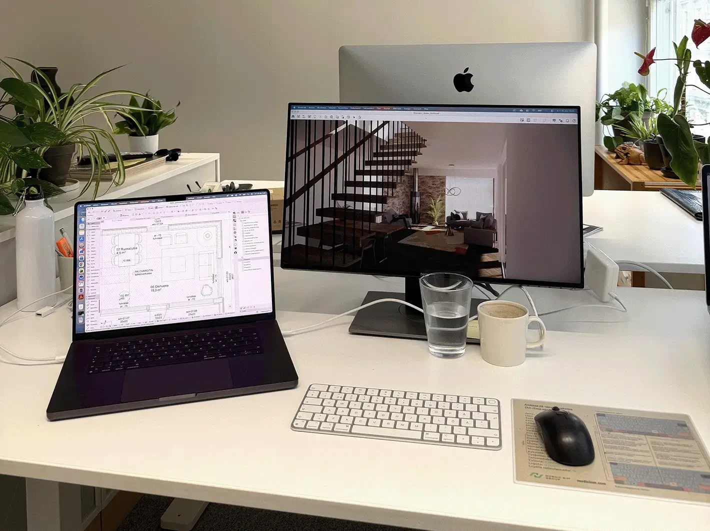
Working drawings are an essential part of every construction project. They give a detailed visual representation of a building's design and specifications, and they act as a shared tool for everyone involved. You simply cannot build anything correctly without good working drawings.
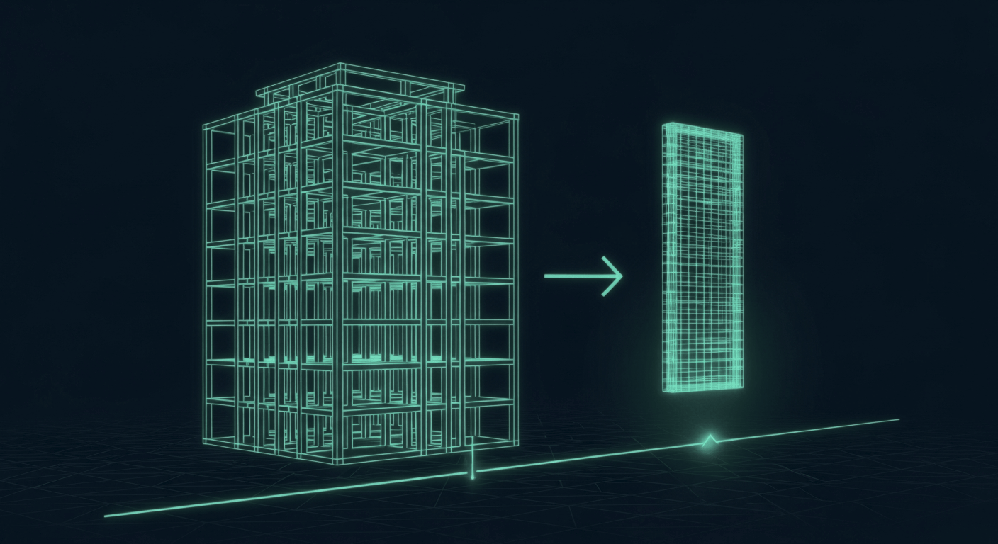
Traditionally, working drawings have been slow and resource heavy to produce. That was before. Today you can pull highly detailed working drawings straight out of the BIM tool with a few keystrokes.
So what do you actually need to know about working drawings? What do they contain, what do they mean for a project, how are they used and what should you focus on or avoid when working with them? We will take you through all of it and a little more.
The important working drawings
Working drawings are technical drawings that show the details of how a structure is built. They carry information on dimensions, materials, construction methods and more. Where a concept sketch or architectural drawing deals with the overall picture, working drawings go right down to every component and solution.
They play a critical role because they communicate every detail clearly and accurately to all parties. They help make sure each part of the building is constructed to specification, and they cut the risk of misunderstandings and errors during construction.
In practice this means you can produce drawings that cover every discipline and every level of a building. There are effectively no limits, which is good, because almost nobody on a project can do without a detailed description of the work to be carried out.
Different types of working drawings
Working drawings can be grouped into several types, each with its own purpose.
Architectural drawings show the building's design, layout and aesthetic aspects, including floor plans, elevations and sections.
Structural drawings focus on the load bearing elements such as foundations, columns, beams and walls.
Mechanical and electrical drawings cover the HVAC systems, electrical installations, lighting and other building services.
Detail drawings show specific parts of the building in greater depth, such as doors, windows, stairs and other complex assemblies.
Landscape drawings set out the design of outdoor areas, including ground planning, planting and other landscape elements.
Coordination drawings make sure every discipline is aligned and that there are no clashes between systems and components.
Typical examples include floor plans that show room layout and dimensions, sections that illustrate heights and structural detail, and detail drawings that show specific construction details such as door and window frame assemblies.
The process of creating working drawings
Creating working drawings runs through several stages, from design to finished drawing. It starts with concept design, where the first sketches and ideas are worked up. The design is then developed further with more detailed drawings, and in the detailed design phase the technical details and specifications are finalised.
The drawings are reviewed and approved by the relevant parties before they are used on site. Involving other disciplines at this point gives you feedback early and surfaces any clashes before they reach the building site.
Key tools for producing working drawings include CAD software such as Archicad, AutoCAD and Revit, used to create accurate and detailed digital drawings, together with BIM tools for coordination and clash detection on larger projects.
You can now also keep fully digital working drawings on site, so up to date drawings are always available no matter where you are in the project. Where teams once printed huge paper versions of every detail, they now carry them on a phone or tablet. That makes it easy for people in the field to follow the plan, and it lets project management make changes or correct errors simply and cost effectively.
Best practice
When you produce working drawings, accuracy and detail are everything. The drawings should contain all the information needed to avoid misunderstandings. Quality control should run regularly so errors are caught and fixed early, and it pays to follow standardised drawing conventions and symbols.
Common mistakes to avoid include missing detail, wrong dimensions and poor coordination between disciplines, which can lead to conflicts on site. This is exactly why modelling a building digitally in a BIM tool turns out to be so effective. The technology lets you avoid errors, spot gaps early and keep the whole project running well.
Digital versus manual working drawings
Digital working drawings bring real advantages. They are easy to edit, store and share, they make it simpler to collaborate with other parties and they raise efficiency by reducing the risk of errors. They are also more sustainable, both economically and environmentally. The trade offs are a dependence on technology and the need for training.
Manual working drawings offer a hands on approach and independence from technology, but they are time consuming to produce and hard to edit. The move to digital drawings delivers clear gains in efficiency and collaboration across the project.
How to read working drawings
Reading working drawings calls for an understanding of the basic symbols and notations. Interpreting dimensions, scales and notations correctly is what lets you understand what a drawing actually says. The symbols represent different elements such as doors, windows and electrical components.
There are architectural, structural and mechanical symbols, expressed through lines of different weights, circles and specific marks that indicate everything from positions to diameters and type specifications.
Measurements and dimensions are shown with lines marking the distance between points, with values placed to give exact figures. Text notes add extra information such as material descriptions and special instructions. Reference symbols such as arrows and circles point to details or refer you to other drawings.
To read working drawings well you need to understand what the symbols mean, interpret dimensions and scales correctly and read the notations carefully so nothing is missed. Knowing these standards is what keeps communication clear and the build accurate.
The role in project coordination
Working drawings are an important tool in every project. They are used to make sure all parties agree on the project's specifications, and they act as a common reference point for everyone on site.
This helps coordinate the work and keeps the project on plan. Good communication and coordination are decisive in keeping things running smoothly, and this is exactly where a BIM coordinator comes in.
To sum up, working drawings are essential to every successful construction project. Their accuracy and level of detail are what make sure the building is constructed to the design specification. By following best practice, avoiding common mistakes and making the most of digital tools, you can be confident your working drawings are effective and reliable.
Frequently asked questions
What are working drawings
Working drawings are technical drawings that show how a structure is built, with the dimensions, materials and construction methods needed to build to specification.
What types of working drawings are there
Common types include architectural, structural, mechanical and electrical, detail, landscape and coordination drawings.
How are working drawings made today
They can be pulled straight from a BIM model. The model holds the building's data, so accurate, detailed drawings for every discipline come out with a few keystrokes.
What is the difference between working drawings and architectural drawings
Architectural drawings deal with the overall design, while working drawings go right down to the detail of every component and solution needed to build it.
Want to pull accurate working drawings straight from the model? Explore Archicad, or talk to us about putting BIM to work in your projects.