![nordicbim_logo.png]](https://www.nordicbim.com/hs-fs/hubfs/Imported%20images/nordicbim_logo.png?height=40&name=nordicbim_logo.png)
Summary and basic concepts
A local coordinate system is the project's common coordinate system to which all models are published. Its origin is placed near the building site—never inside the building or site area—such that the building and site are located east and north of the origin (positive coordinates). This is laid out for example in the european openBIM Harmony documentation.
Origin Location
The local coordinate system origin is placed at most a few hundred meters from the site, at round coordinate values on the base map (for example, E/N values ending in 50 m or 100 m multiples). In practice, this often means the nearest suitable coordinate grid intersection point on the survey map.
North Direction
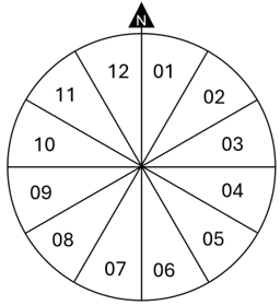
The local coordinate system is oriented toward map north of the survey map, like a site plan drawing traditionally. Note that modeling is still done oriented to the building, and this north direction is assignes with the Survey Point.
Control Points and control objects
The origin and two other points (P1 to the east, P2 to the north) are recorded in the BIM documentation as control points for project alignment. They are shown in the model using alignment objects (see openBIM Harmony), which allow models to be aligned visually in the combined model.
Archicad Workflow of survey map in three positions
Use three worksheets to position the base map in different coordinates:
-
"Survey Map" (map in world coordinates, origin at the drawing origin),
-
"Survey Map at Local Coordinate System" (map shifted, local coordinate system origin at the internal origin), and
-
"Survey Map at Internal Coordinate System" (map rotated to the building direction).
-
Lock the control objects and Survey Point at the end.
Local Coordinate System Control Points – Detailed Steps
Control points, typically an origin and two other points, 'P1' and 'P2', are alignment points that assist in using the local coordinate system. For control points, coordinate value pairs are recorded in the BIM documentation in both the local coordinates and the survey map global coordinates. This allows map coordinate data to be accurately aligned to the local coordinate system and vice versa.
Control points are represented in the model using alignment objects so that correct model alignment in the combined model is easy to verify visually.
Creating Local Coordinate System Control Points
Defining control points begins by selecting the local coordinate system origin—the first control point.
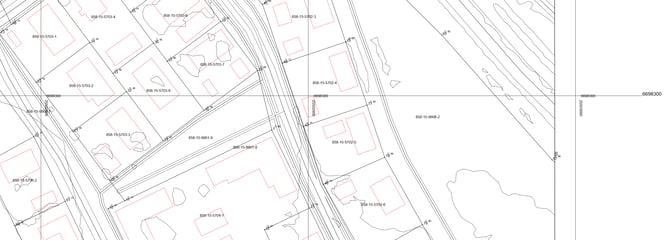
Preferably use a survey map that displays coordinate grid lines; otherwise, finding coordinate readings is more laborious. For example, Cetopo map materials include a clear coordinate grid as shown in the image. If necessary, you can request coordinate readings marked on the map from the city's mapping department, or prepare them yourself in a DWG.
Attaching the Base Map to the Model
The map is imported into a worksheet, where it is easiest to work with. Later, for example when creating a site plan, you can copy the map to a layer on a building dotrey, but otherwise it is best to keep the map separate from the model in a worksheet and use it as a reference image. This way the map cannot be accidentally edited and does not cause problems due to its large scale.
-
Create an independent drawing in Archicad named "Survey Map". Attach the map DXF/DWG to the drawing as an external reference.
-
Position the map origin at the drawing origin, typically this results in the actual map drawing being located (too) far from the origin. (The origin may need to be marked in the DXF/DWG file in advance so you can align it reliably.)
-
If the map does not yet show coordinates, they can be displayed using a Coordinate Dimensions object. Explode the objects to text finally so their values cannot change later.
Selecting the Local Coordinate System Origin and Two Other Control Points
The origin location must be selected so that the site and its lots are in the local coordinate system east and north of the origin—that is, their coordinate values are on positive axis directions. When selecting the origin, also ensure that no broader surrounding model content is positioned above the origin or other control points—using the points is most efficient if they do not become easily obscured behind model geometry.
Control points are most practically placed at round coordinate values on the base map—E/X and N/Y readings ending in 50 or 100 meters. Map coordinates are already large numbers anyway, and as round values like these they are easier to work with.
The first control point is thus the local coordinate system origin, and P1 to the east and P2 to the north are located, for example, 50 or 100 meters from the origin. The building geometry itself always has variations due to the design phase, and even site corner points may be refined during the project, so independence of the control points from the actual site geometry is most reliable.
-
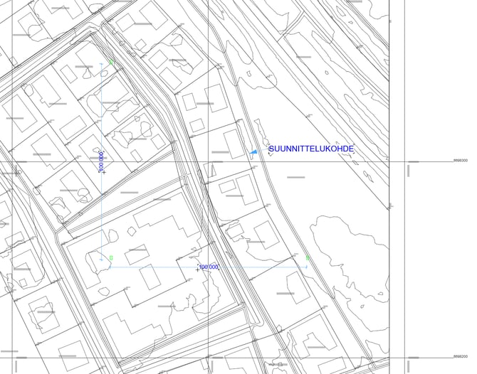
Mark the origin and control points P1 and P2 on the map on the worksheet -for example, at the corner of a 1×2 m rectangle, or with the 'coordination pie' wedge as described by openBIM Harmony.
-
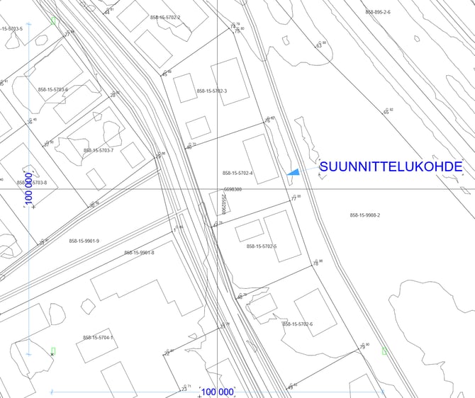
Then create a new worksheet, "Survey Map at Local Coordinate System," and copy the map drawing and markings to it. Move the map in this drawing so that the local coordinate system origin is at the internal origin.
-
Create one more worksheet, "Base Map at Internal Coordinate System," and copy the map drawing and markings to it. Rotate them now so that the map direction matches the building direction in the model. Using this rotated map, you set the Survey Point's north direction in the model, and later you can copy it for use in the site plan.
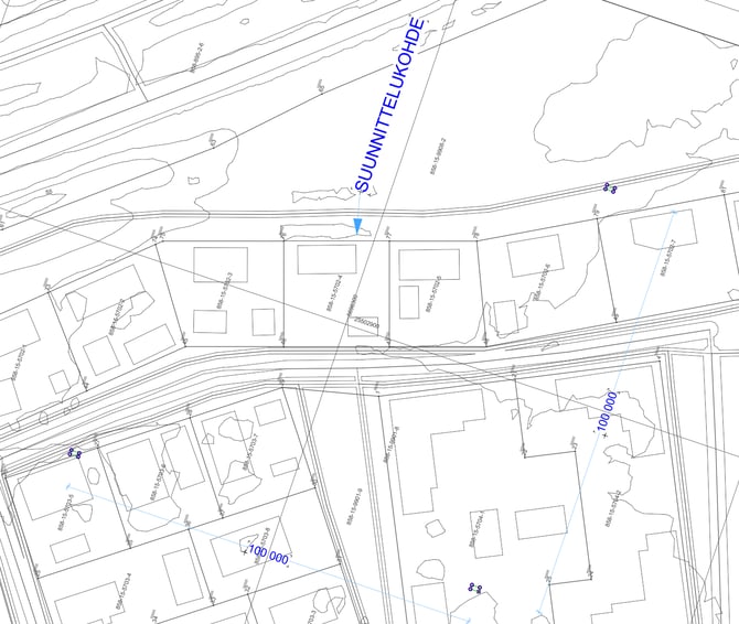
Now that the control points are clear, mark them in the model using control objects - with these, you can verify model alignment truly easily and reliably!